
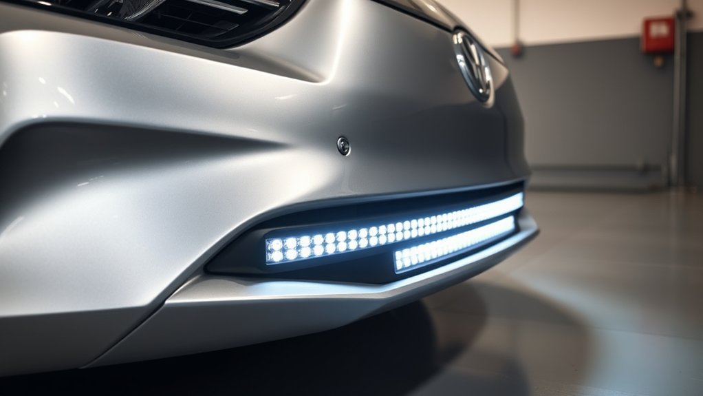
Installing an LED light bar can improve visibility for off-road driving, work sites, farms, trails, and other low-light tasks, but the installation must protect the vehicle, the wiring, and other road users. The safest approach is to use vehicle-specific brackets, a correctly sized fused circuit, weather-sealed connections, and the instructions supplied with both the light bar and your vehicle.
Quick Answer
Mount the bar on a secure vehicle-specific bracket, route a dedicated fused harness away from heat and moving parts, use a relay or properly rated factory upfitter circuit, connect to an approved ground, then test and aim the beam. Check the owner’s manual and applicable state laws before using it on public roads.
Key Takeaways
- Verify the light bar’s voltage, rated current, bracket fit, and wiring method for your exact vehicle, model year, and equipment package.
- Protect the positive feed with the manufacturer-specified fuse or circuit breaker placed close to the power source.
- Use a relay unless the light is connected to a factory upfitter circuit that is rated for the full load.
- Do not drill near airbags, sensors, cameras, radar units, hidden wiring, brake lines, fuel lines, cooling components, or high-voltage cables.
- Auxiliary-light laws vary by state. A bright off-road light bar may need to remain off or covered on public roads.
At a Glance
| Time Required | About 1–4 hours; longer when custom brackets, drilling, interior switch routing, or troubleshooting are required |
| Difficulty | Moderate; advanced if the vehicle needs custom fabrication, CAN-bus integration, or work near hybrid/EV systems |
| Tools Needed | Socket and wrench set, torque wrench, trim tools, drill only if approved, crimper, wire stripper, multimeter, safety glasses, gloves, and weather-sealed connectors |
| Cost | Varies by light bar, vehicle-specific brackets, wiring harness, switch system, and professional labor |
Warning: Follow the battery-disconnection procedure in the owner’s manual before electrical work. On a hybrid or EV, stay within the approved low-voltage accessory system and never cut, probe, move, or fasten anything to orange high-voltage cables or labeled high-voltage components. Use a qualified installer when the correct circuit or mounting area is uncertain.
Understanding the Benefits of Installing an LED Light Bar
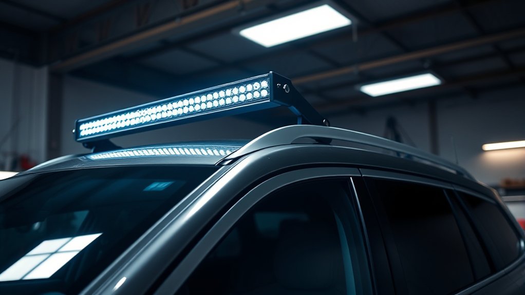
A properly selected LED light bar can provide a wide flood pattern, a long-range spot pattern, or a combination of both. That extra light can help during off-road travel, property maintenance, recovery work, snow removal, or other tasks performed away from normal street lighting.
LED technology is generally efficient and durable, but the actual current draw, light output, beam pattern, service life, and environmental protection vary by product. Do not rely on a generic lumen or lifespan claim. Compare the manufacturer’s rated wattage, current, beam pattern, operating voltage, warranty, and test information. General LED technology can use less energy than incandescent lighting, but a large light bar can still place a meaningful load on a vehicle’s 12- or 24-volt system. The ENERGY STAR overview of LED lighting explains the efficiency advantages of LEDs.
For wet or dusty use, check the product’s documented ingress-protection rating and connector design rather than accepting a broad “waterproof” claim. Also confirm that the mounting system can resist vibration without allowing the beam aim to shift.
A light bar is only an upgrade when the mount is secure, the circuit is protected, the beam is aimed responsibly, and the light is used where the law allows it.
Check Compatibility, Legality, and Safety Before Installation
Verify Vehicle and Electrical Compatibility
Start with the owner’s manual, the light bar manual, and any vehicle body-builder or upfitter guide. Verify information for the exact VIN, model year, engine or powertrain, trim, and factory option package because fuse locations, approved pass-through points, auxiliary-switch ratings, grounding points, airbag locations, and sensor layouts can differ even within the same model.
- Confirm whether the accessory system is 12 volts or 24 volts.
- Use the light bar’s rated current when available. If only wattage is listed, current is approximately watts divided by system voltage, but the manufacturer’s measured current is more reliable.
- Check the rating of any factory auxiliary or upfitter switch. Some switches control a relay rather than carrying the full lamp load.
- Confirm that the charging system or DC-to-DC converter can support the added load, especially when several accessories run at once.
- Do not splice into factory headlamp, camera, radar, airbag, or network wiring unless the vehicle manufacturer specifically approves that connection.
Many late-model vehicles provide dedicated upfitter circuits with specified fuse ratings and wire locations. Use those provisions only within their published limits; do not assume two similar-looking vehicles are wired the same way.
Understand Public-Road Lighting Rules
There is no single nationwide rule that makes every aftermarket light bar legal for road use. The federal lighting standard, FMVSS No. 108, governs required lighting and replacement lighting equipment. NHTSA has also explained that states may regulate supplemental lamps and that aftermarket equipment must not impair required safety equipment. Review the NHTSA auxiliary-lighting interpretation and your state vehicle code before public-road use.
State and local rules may control lamp color, mounting height, the number of forward-facing lamps, covers, flashing functions, beam aim, and when the light may be switched on. A “DOT” marking or an advertisement that says “street legal” does not override those rules. When legality is uncertain, keep an off-road light bar off on public roads and use the vehicle’s compliant factory lighting.
Commercial vehicles have additional requirements. Federal rules for commercial motor vehicles state that auxiliary driving lamps must be aimable, securely mounted, and used with—not instead of—required headlamps. See 49 CFR 393.24.
Protect Airbags, ADAS, and High-Voltage Systems
Before drilling or routing wire, inspect both sides of the proposed area. Avoid curtain airbags and their deployment paths, airbag sensors, seat-belt pretensioner wiring, forward cameras, radar units, parking sensors, radiator airflow, active grille shutters, brake lines, fuel lines, washer hoses, sunroof drains, and factory harnesses.
On electric and hybrid vehicles, the accessory lighting normally uses the low-voltage system, not the traction battery. NHTSA notes that the high-voltage battery is separate from the 12-volt system and recommends following the owner’s manual for maintenance and related operations. See NHTSA’s electric- and hybrid-vehicle safety guidance. If the installation path comes near orange cables or high-voltage labels, stop and use a qualified technician.
Note: Roof drilling can damage corrosion protection, headliner wiring, curtain airbags, and water-management channels. A vehicle-specific no-drill bracket is usually the lower-risk choice.
Essential Tools and Materials for Your Installation
Gather the tools and electrical components before removing trim or mounting hardware. A complete kit reduces the chance of leaving an unfused wire, exposed terminal, or loose bracket while waiting for another part.
Required Tools Overview
- Socket and wrench set sized for the supplied hardware
- Torque wrench and the bracket manufacturer’s torque specifications
- Plastic trim-removal tools
- Wire stripper and ratcheting crimper for the selected terminals
- Digital multimeter with intact, correctly rated test leads
- Drill, step bit, center punch, and rust protection only when drilling is approved and the hidden area has been inspected
- Heat gun for adhesive-lined heat-shrink tubing
- Fine-tooth saw or fabrication tools only if the bracket instructions require modification
- Flashlight, measuring tape, marker, and painter’s tape for mock-up work
Avoid using sheet-metal screws as a universal mounting solution. Any new hole can weaken a panel, expose bare metal, create a leak, or damage a hidden component. Use the bracket manufacturer’s hardware and reinforce the mounting surface when required.
Essential Wiring Components
- Vehicle-compatible wiring harness: It should be rated for the light bar’s voltage and current and should include suitable wire insulation for an engine-bay environment.
- Fuse or circuit breaker: The protective device must be sized to protect the wire and installed close to the power source. Eaton explains that battery-terminal fuses are designed to protect conductors at the battery. See Eaton Bussmann battery-terminal fuse guidance.
- Relay: A relay allows the dashboard switch or trigger wire to control the lamp without carrying the full lamp current. Use the relay and pinout shown in the harness instructions.
- Weather-sealed connectors: Use correctly crimped, sealed automotive connectors or adhesive-lined heat-shrink terminals. Do not rely on twisted wires and electrical tape.
- Abrasion protection: Use split loom, braided sleeve, grommets, edge guards, and cushioned clamps where needed.
- Mounting hardware: Use corrosion-resistant bolts, washers, locking hardware, and threadlocker only when specified.
Suggested Safety Gear
Wear safety glasses when drilling, cutting, or working under the vehicle. Gloves help with sharp brackets and panel edges, but remove loose gloves around rotating tools. Use hearing protection when drilling or cutting metal. Support lifted vehicles with correctly rated stands on a stable surface; never work under a vehicle supported only by a jack.
Step-by-Step Guide to Mounting Your LED Light Bar
Complete the mechanical installation before making the final battery connection. Keep the fuse removed from the new harness while routing and terminating wires so the accessory feed cannot become live unexpectedly.
Selecting Mounting Location
Compare roof, grille, bumper, bull-bar, and rack mounting options. The best location is structurally sound, allows the lamp to be aimed, does not block airflow or sensors, and provides a protected path for the harness.
- Mock up the light and brackets with painter’s tape before drilling or tightening.
- Turn the steering from lock to lock and check suspension, hood, door, hatch, and wiper movement.
- Confirm the bar does not obstruct the driver’s view or reflect strongly from the hood, windshield, mirrors, or roof.
- Check the backside of every proposed hole and keep clear of airbags, wiring, hoses, lines, and structural seams.
- Leave room around cooling fins and vents required by the light manufacturer.
Securing Light Bar
Install the brackets in the sequence shown by the manufacturer. Start all fasteners by hand, align the bar, and tighten the mount evenly. Use longer bolts only when the bracket maker or a qualified fabricator confirms the correct diameter, grade, thread engagement, and clearance.
Torque fasteners to the specified value. Over-tightening can crush a bracket, strip threads, crack a housing, distort sheet metal, or damage a roof channel. Under-tightening can allow vibration and beam movement. After the first drive on rough ground, recheck the hardware when the light has cooled.
Aim the Light Before Final Tightening
Leave the pivot bolts snug enough to hold position but loose enough for adjustment. Park on level ground and aim the beam according to the light manufacturer’s instructions. Prevent the hotspot from shining into oncoming traffic, mirrors, homes, campsites, or work areas where it can blind another person.
Pro Tip: Temporarily power the bar with the completed fused harness before fully tightening the pivot bolts. Final aiming is easier when you can see the actual beam pattern rather than judging the housing angle.
Wiring Connections Explained
A dedicated harness usually has a battery feed, an inline fuse, a relay, a switch or trigger lead, an output to the light, and a ground. The positive feed supplies current; the ground is the return path to the battery. It is not a route for “excess electricity.”
Do not assume wire colors or relay terminal numbers are universal. Connect each lead according to the markings and diagram supplied with the harness. Keep the battery feed disconnected and the inline fuse removed until mounting, routing, crimping, and inspection are complete.
Essential Wiring Steps for Your LED Light Bar
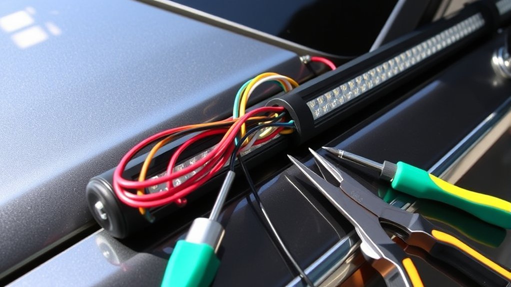
Use this sequence as a general guide, then follow the light bar, harness, and vehicle instructions when they differ.
| Step | Action | Safety Check |
|---|---|---|
| 1 | Verify the vehicle, light, bracket, harness, fuse, relay, and switch ratings. | Use information for the exact VIN and model year. |
| 2 | Follow the owner’s manual to power down the vehicle and disconnect the low-voltage battery when required. | Preserve radio codes, memory procedures, and hybrid/EV requirements. |
| 3 | Mount the light and relay, but leave the harness fuse removed. | Mount the relay in a protected position and orientation specified by its maker. |
| 4 | Route the harness away from exhaust parts, sharp edges, fans, belts, steering, suspension, and pinch points. | Use loom, grommets, clamps, and slack for normal movement. |
| 5 | Pass the switch lead through an approved factory grommet or upfitter pass-through. | Do not pierce a grommet beside an existing harness unless the manufacturer permits it. |
| 6 | Crimp and seal the power, load, trigger, and ground connections according to the harness diagram. | Perform a pull test on each crimp and protect exposed metal. |
| 7 | Inspect continuity, polarity, fuse rating, wire support, and clearances before energizing. | Never place a multimeter in current mode directly across the battery. |
| 8 | Reconnect the battery as directed, install the correct fuse, test the light, and complete final aiming. | Stop immediately if wiring heats, smokes, arcs, or repeatedly blows a fuse. |
Let’s Get Your LED Light Bar Wired Up Right
Wiring Harness Essentials
Choose a harness that matches the lamp’s operating voltage and rated current. KC HiLiTES’ official wiring support recommends an inline fuse near the battery and a relay-based harness for typical light-bar installations. See the KC light-bar wiring guidance.
Wire size must account for current, total circuit length, allowable voltage drop, insulation temperature, and the route through the vehicle. A longer run or higher current may need a larger conductor. The fuse must protect the smallest wire in the circuit and must never be increased simply because the original fuse opens.
Calculate Current and Select the Wire, Fuse, and Relay
Use the manufacturer’s current rating whenever possible. For a rough check, divide rated watts by system voltage. A 120-watt light on a 12-volt system is roughly a 10-amp load, but real current can change with voltage and driver electronics. Select the wire and protective device from the manufacturer’s chart or a recognized automotive wiring guide, not from wattage alone.
- Wire: Must safely carry the load over the full round-trip length with acceptable voltage drop.
- Fuse: Must protect the wire and be within the limits of the harness and lamp instructions.
- Relay: Must be rated for the lamp’s continuous current and inrush characteristics, with suitable environmental protection.
- Switch or trigger: Must carry only the current it is designed for. A small dashboard switch usually triggers the relay rather than powering the bar directly.
Relay Connection Process
Many four-pin automotive relays use terminal 30 for battery power, 87 for the load, and 85 and 86 for the coil. However, do not wire by memory. Five-pin relays, solid-state relays, prewired harnesses, and relays with suppression diodes can use different internal arrangements or require specific coil polarity.
- Read the diagram printed on the relay or supplied with the harness.
- Mount the relay close enough to the power source to keep the high-current feed short, while protecting it from direct heat, spray, and impact.
- Connect the fused power feed, lamp output, switch trigger, and ground exactly as shown.
- Secure the relay with its mounting tab or approved holder rather than leaving it suspended by the wires.
Grounding Techniques Explained
Use a manufacturer-approved chassis ground or a direct negative-battery connection when the instructions call for it. A good chassis ground has solid metal contact, adequate conductor size, short length, and protection from corrosion.
- Do not ground through paint, rust, a hinge, a rubber-mounted bracket, or a thin decorative panel.
- Clean only the approved contact area and use the specified terminal, washer, and fastener.
- After tightening, protect the connection with an approved corrosion barrier without insulating the metal-to-metal contact.
- Check resistance or voltage drop under load; a continuity beep alone may not reveal a weak ground.
Route Wires Through the Engine Bay and Firewall
Follow existing harness routes where practical, but do not bind the new wire so tightly that it rubs against factory wiring. Keep it away from exhaust manifolds, turbochargers, radiators, fans, belts, pulleys, steering shafts, pedals, hinges, suspension travel, and sharp metal edges.
Use an approved factory pass-through for the switch lead. Fit a grommet wherever wire passes through metal and seal the opening with a vehicle-safe method that does not trap water. Inside the cabin, secure the wire so it cannot interfere with pedals, steering, knee airbags, side-curtain airbags, seat tracks, or trim fasteners.
Complete the Power Connection
After every connection has passed a visual and mechanical inspection, reconnect the battery in the sequence specified by the owner’s manual. Install the correctly rated fuse last. Never bypass the fuse for testing, and never replace it with a larger value to stop nuisance openings. A fuse that opens repeatedly signals a short, wrong fuse rating, undersized circuit, defective lamp, or wiring error that must be corrected.
How to Test Your LED Light Bar for Proper Functionality?
Test the installation in stages. Keep people clear of the front of the vehicle and avoid shining the beam toward traffic or occupied buildings.
| Check | Method | Acceptable Result |
|---|---|---|
| Mechanical security | Push and pull the bar and brackets by hand. | No looseness, panel flex beyond design, or contact with nearby parts. |
| Polarity and supply voltage | Measure voltage at the lamp connector with the circuit on. | Voltage is within the lamp manufacturer’s operating range. |
| Relay and switch | Operate the switch several times. | Consistent operation without chatter, flicker, heat, or delay. |
| Voltage drop | Measure across the positive and ground sides while the light is on. | Within the limits in the lamp or wiring instructions. |
| Heat and chafe | Run the light for the manufacturer’s recommended test period, then switch it off and inspect. | No hot connectors, softened insulation, odor, rubbing, or discolored terminals. |
| Beam aim | Check on level ground against a safe surface. | Beam serves the intended work or off-road area without hazardous glare. |
After the first drive, inspect the harness for movement and recheck fasteners after the components cool. Verify that no warning lights, camera faults, parking-sensor errors, radio interference, or battery-management alerts appeared.
What to Do If Your LED Light Bar Isn’t Working?
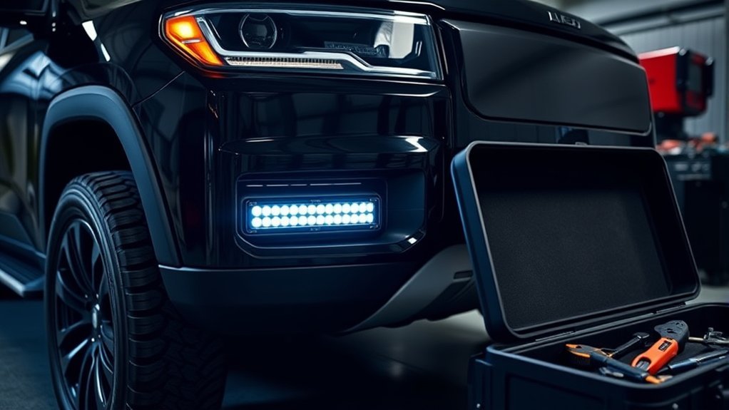
Start with the simplest checks and do not replace a fuse until the reason it opened is understood. Turn the circuit off before moving wires or unplugging connectors.
| Symptom | Likely Causes | What to Check |
|---|---|---|
| No light and no relay click | No trigger power, bad switch ground, disconnected harness, or open control fuse | Switch input/output, relay coil circuit, connector seating, and vehicle upfitter settings |
| Relay clicks but bar stays off | Open main fuse, poor power feed, bad ground, wrong relay pinout, or failed lamp | Voltage at relay input/output and at the lamp under load |
| Flickering or dim output | Loose connector, high-resistance ground, undersized wire, voltage drop, weak charging system, or incompatible control module | Loaded voltage-drop test, crimp quality, ground point, and harness rating |
| Fuse opens immediately | Short to ground, reversed connection, pinched wire, wrong relay wiring, or defective lamp | Disconnect the lamp, inspect the full run, and test each section before fitting another correct-size fuse |
| Fuse opens after several minutes | Overload, undersized wire, wrong fuse type, overheating connector, or failing driver | Rated current, actual current with a proper meter setup, connector temperature, and manufacturer specifications |
| Water or condensation inside lamp | Damaged seal, housing crack, blocked vent, or pressure-washer intrusion | Warranty instructions; do not drill the housing or cover designed vents |
If the problem involves a factory control module, CAN-bus message, repeated battery drain, melted connector, high-voltage vehicle system, or unknown wiring modification, stop and use a qualified automotive electrician or manufacturer-approved installer.
Top Maintenance Tips for Your LED Light Bar
- Clean the lens: Use mild soap, water, and a soft cloth. Avoid abrasive pads and harsh solvents.
- Check the aim: Re-aim the bar if vibration, impact, rack movement, or bracket service changes its position.
- Inspect fasteners: Look for looseness, cracked brackets, elongated holes, rust, and panel fatigue.
- Inspect the harness: Check for chafing, hard or brittle insulation, loose clamps, heat damage, corrosion, and water in connectors.
- Check electrical performance: Investigate flicker, delayed operation, relay chatter, blown fuses, or a hot connector immediately.
- Protect the housing correctly: Do not coat heat sinks, vents, lenses, or connectors with an unapproved sealant. Follow the lamp manufacturer’s maintenance instructions.
Inspect the installation after off-road trips, deep water, pressure washing, collisions, rack removal, battery service, or any work near the harness. A six-month inspection is a reasonable minimum for lightly used vehicles, but severe service needs more frequent checks.
Choose the Right Wiring Option for Your LED Light Bar
The safest wiring method depends on the vehicle and the electrical load. Do not reuse an old lighting circuit unless its wire size, fuse, connector, switching method, and vehicle approval are all confirmed for the new lamp.
| Wiring Option | Best For | Key Requirement |
|---|---|---|
| Dedicated fused relay harness | Most conventional 12- or 24-volt installations | Harness, fuse, relay, connectors, and wire must match the load and environment |
| Factory auxiliary or upfitter switch | Vehicles with documented accessory circuits | Stay within the exact fuse and current rating and use the correct blunt-cut wire or connector |
| Upfitter switch as relay trigger | Loads that exceed the direct rating of the factory switch circuit | The factory circuit controls a separate correctly rated fused relay circuit |
| Programmable or CAN-controlled accessory module | Complex late-model vehicles or multiple accessories | Use a vehicle-compatible module and professional configuration where required |
Safety Tips for Installing Your LED Light Bar
| Hazard | Safe Practice |
|---|---|
| Unexpected power or short circuit | Follow the owner’s manual power-down procedure and leave the new circuit’s fuse out until final testing. |
| Battery damage or fire | Use a correctly sized protective device close to the power source and cover the positive terminal. |
| Hidden component damage | Inspect both sides before drilling and verify airbag, sensor, line, hose, and harness locations. |
| Hybrid/EV high voltage | Do not touch orange cables or high-voltage components; use the approved low-voltage accessory procedure. |
| Vehicle movement | Park on a flat surface, set the parking brake, chock wheels when needed, and use stands if the vehicle is raised. |
| Glare to other road users | Aim responsibly and keep noncompliant off-road lighting off or covered on public roads. |
Professional installation is the safer choice when the job requires roof drilling, welding, custom fabrication, high-current design, advanced diagnostics, airbag-area trim removal, CAN-bus integration, or work near hybrid/EV high-voltage equipment.
Frequently Asked Questions
Can I install an LED light bar on any vehicle?
Most vehicles can support some form of auxiliary lighting, but the bar, bracket, voltage, current draw, switch method, and mounting location must suit the exact vehicle. Check the owner’s manual and model-year-specific upfitter information. Hybrids, EVs, vehicles with ADAS sensors, and vehicles without approved mounting points may need a professional installation.
How long does LED light bar installation usually take?
A bolt-on installation with a complete vehicle-specific harness may take about one to four hours. Custom brackets, drilling, interior switch routing, corrosion protection, complex trim removal, or electrical troubleshooting can take longer. Do not rush the inspection, fuse selection, wire protection, or aiming steps.
Do I need a permit to install or use an LED light bar?
There is no single nationwide permit rule for all auxiliary lights. State and local laws may restrict lamp color, height, number, covers, flashing modes, beam aim, inspection compliance, and when the light can be used. Check the current vehicle code where the vehicle is registered and where it will be driven.
Can I use my light bar during the day?
Only when the lamp, color, mounting, beam, and use comply with the applicable law. Many high-output bars are intended for off-road or work-site use and can create dangerous glare even in daylight. Keep the bar off on public roads unless you have confirmed that its use is legal in that location.
What commonly causes an LED light bar to fail?
Common causes include a blown fuse, loose crimp, corroded connector, poor ground, damaged harness, wrong relay wiring, excessive voltage drop, water intrusion, overheating, or a failed LED driver. Test the circuit under load and repair the cause rather than fitting a larger fuse.
What size fuse and wire should I use?
Use the sizes specified by the light bar or harness manufacturer. Wire size depends on current, circuit length, voltage drop, insulation rating, bundling, and temperature. The fuse must protect the smallest wire in the circuit and remain within the ratings of the lamp, relay, connectors, and vehicle accessory system.
Can I wire a light bar without a relay?
Only when a documented factory upfitter circuit or control module is designed to carry the full load directly. A typical small dashboard switch should not carry light-bar current. For most standalone installations, a correctly rated relay or solid-state power module is the safer design.
Will an LED light bar drain the battery?
It can if it remains on with the vehicle off, if the trigger circuit is wired to constant power, or if a relay or control module fails. Use an ignition-controlled trigger when appropriate, switch the light off before parking, and investigate any unexplained battery drain.
Conclusion
A successful LED light bar installation depends on more than attaching a bright lamp. Verify compatibility for the exact vehicle, mount the bar without compromising airbags, sensors, structure, or weather sealing, and use a dedicated circuit with the correct wire, fuse, relay, connectors, and ground. Test the system under load, aim it responsibly, and follow state and local rules. When the job involves unknown wiring, custom fabrication, CAN-bus controls, or hybrid/EV high-voltage areas, use a qualified installer.
Sources
- National Highway Traffic Safety Administration — Auxiliary Lighting Interpretation — explains federal treatment of supplemental lighting and the role of state laws.
- Electronic Code of Federal Regulations — 49 CFR 571.108 — federal motor-vehicle lighting standard.
- Electronic Code of Federal Regulations — 49 CFR 393.24 — auxiliary-lamp mounting and aiming requirements for commercial motor vehicles.
- KC HiLiTES — Light Bar Wiring Support — manufacturer guidance on fused relay harnesses and battery-side circuit protection.
- National Highway Traffic Safety Administration — Electric and Hybrid Vehicles — distinguishes the low-voltage accessory system from the high-voltage traction system and directs owners to manufacturer procedures.
- Eaton Bussmann — Battery Terminal Fuses — explains conductor protection at the battery.







Leave a Reply